Re: Woo Hoo! A Big Project!
Posted: Sat Jun 04, 2011 9:05 pm
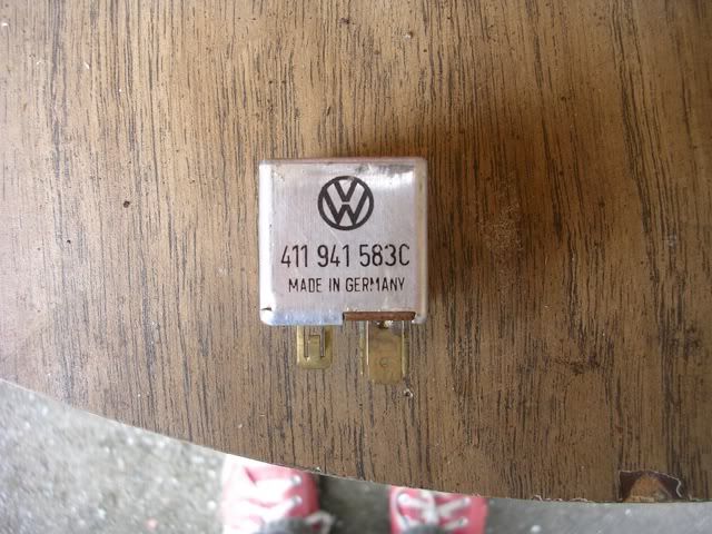
More anti-voodoo today. I realized that in addition to having no power to the headlight that my dip switch was not functioning. It would not hold the high beam position. As a new left side switch runs nearly $200, and the other functions of the switch were just fine, I thought about how I could get high beam with just an intermittent signal from the switch. Then I drove the Kombi to go surfing before dawn one morning and I realized that VW had solved my problem 40 some years ago. Voila, a 1971 VW dimmer relay:
And here's the schematic:
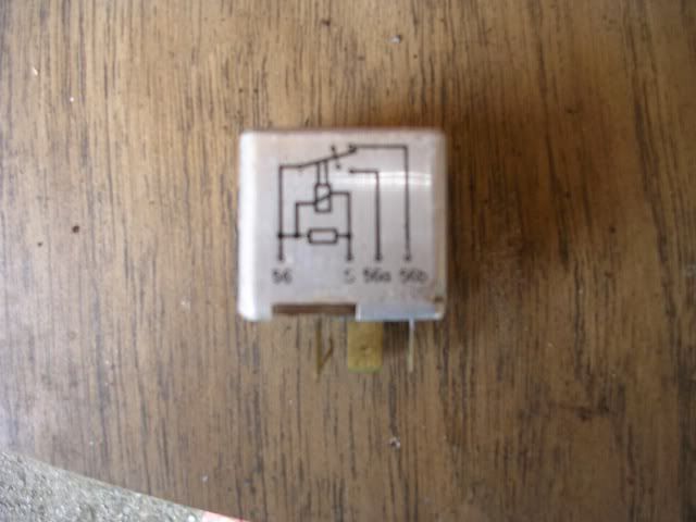
So on this one, hot comes in at 56 and goes out to 56a or 56b. The choice of where it goes changes each time S is momentarily connected to ground. S (the switch circuit) gets its hot also from 56.
Unfortunately, this relay came from my junk pile. It stuck once and shorted inside, taking out my last German voltage regulator. So I went to my VW FLAPS and scored a new one, just $30:
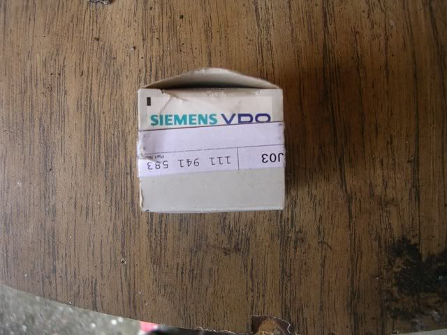
The part number is slightly different, and it's intended for later WCVWs so there's a tiny functional difference. Also note that it's from Siemens/VDO, which makes me smile every time I think of VDO's aftermarket ad campaign from a while ago, "Help Spread VDO!" Clearly it's now, "Help Spread VDO with Siemens!" I'll be just a minute ROFL.
And I'm back. The schematic is different:
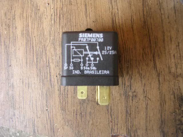
The switch circuit needs its own hot, coming in at 30. No big deal, as I can piggyback on the headlight hot, and it will function just like the earlier one.
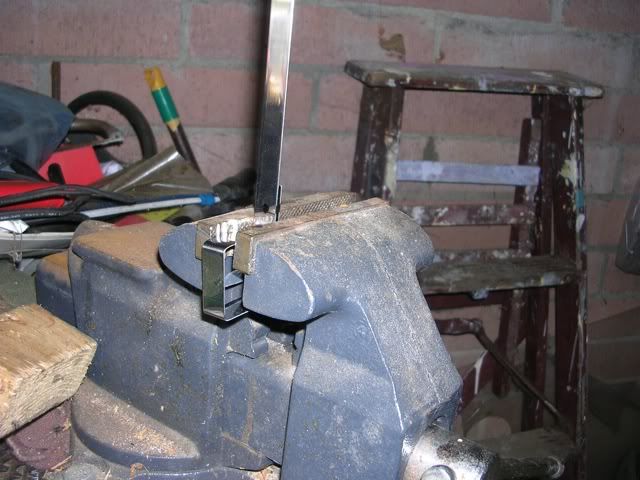
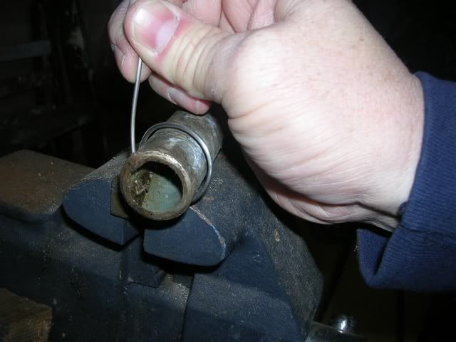
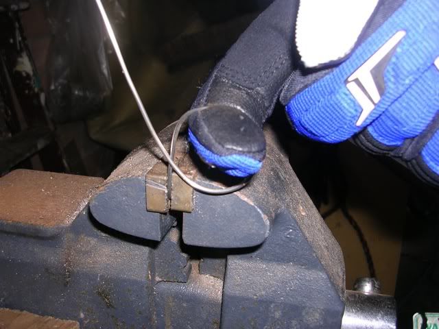
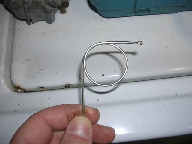
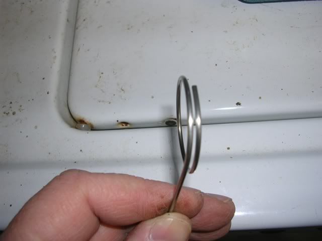
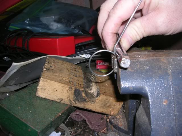
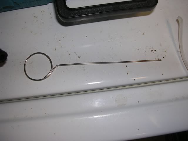
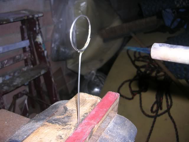
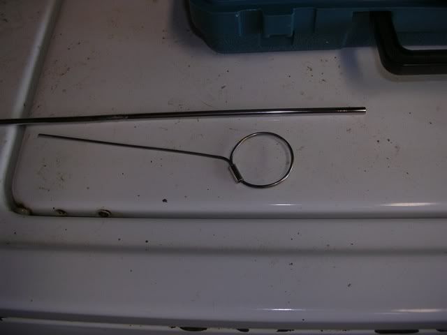
I try where I can, when I'm wiring stuff in, to match the DIN wire color. To make this one go, I needed yellow to go from 56a (low beam) to the junction board, and white to go from 56b (high beam) to the junction board. I also needed yellow/white to go from the main light relay to 56 on the dimmer relay. I didn't want to chase down a funky wire when I only needed a few inches, so I made my own yellow/white:
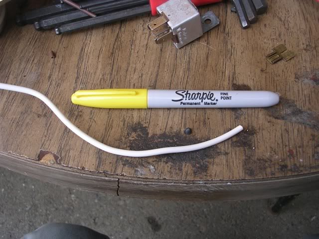
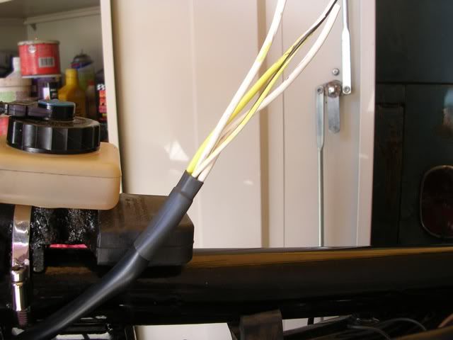
It worked a trick:
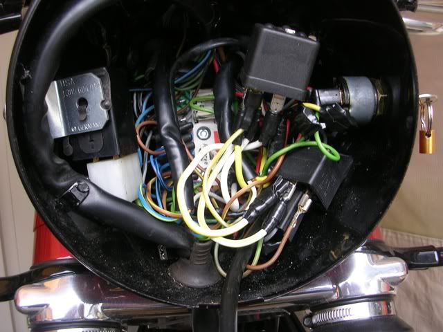
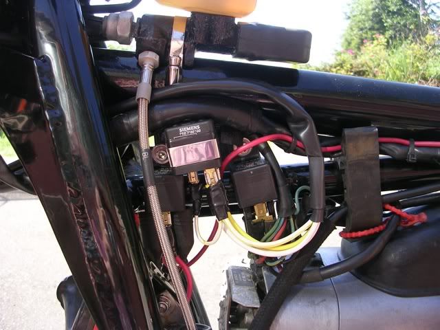
Wiring was like so: New yellow/white from 87 on the light relay to 56 on the dimmer relay. New yellow/white piggybacked from 87 on the light relay to 30 on the dimmer relay. New white from 56a on the dimmer to 56a on the junction board. New yellow from 56b on the dimmer relay to 56b on the junction board. I then connected the yellow/white from the dipswitch to S on the relay, and the white from the dipswitch to a spare ground on the circuit board. The yellow and red wires from the dipswitch are not used. They are taped up and put out of the way.
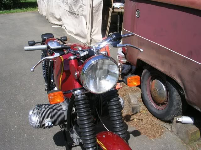
The wiring works great--just a push up on the dipswitch takes it from low to high, and the indicator light should work as I have power to the instrument plug. I'm having some issues getting the headlight to mount to this crowded shell. I may have to relocate the dimmer relay under the tank, in the space made available by the recent starter and horn relay work.

And here's the schematic:

So on this one, hot comes in at 56 and goes out to 56a or 56b. The choice of where it goes changes each time S is momentarily connected to ground. S (the switch circuit) gets its hot also from 56.
Unfortunately, this relay came from my junk pile. It stuck once and shorted inside, taking out my last German voltage regulator. So I went to my VW FLAPS and scored a new one, just $30:

The part number is slightly different, and it's intended for later WCVWs so there's a tiny functional difference. Also note that it's from Siemens/VDO, which makes me smile every time I think of VDO's aftermarket ad campaign from a while ago, "Help Spread VDO!" Clearly it's now, "Help Spread VDO with Siemens!" I'll be just a minute ROFL.
And I'm back. The schematic is different:

The switch circuit needs its own hot, coming in at 30. No big deal, as I can piggyback on the headlight hot, and it will function just like the earlier one.
I try where I can, when I'm wiring stuff in, to match the DIN wire color. To make this one go, I needed yellow to go from 56a (low beam) to the junction board, and white to go from 56b (high beam) to the junction board. I also needed yellow/white to go from the main light relay to 56 on the dimmer relay. I didn't want to chase down a funky wire when I only needed a few inches, so I made my own yellow/white:

It worked a trick:

Wiring was like so: New yellow/white from 87 on the light relay to 56 on the dimmer relay. New yellow/white piggybacked from 87 on the light relay to 30 on the dimmer relay. New white from 56a on the dimmer to 56a on the junction board. New yellow from 56b on the dimmer relay to 56b on the junction board. I then connected the yellow/white from the dipswitch to S on the relay, and the white from the dipswitch to a spare ground on the circuit board. The yellow and red wires from the dipswitch are not used. They are taped up and put out of the way.
The wiring works great--just a push up on the dipswitch takes it from low to high, and the indicator light should work as I have power to the instrument plug. I'm having some issues getting the headlight to mount to this crowded shell. I may have to relocate the dimmer relay under the tank, in the space made available by the recent starter and horn relay work.
