OK, the reasoning behind the move was:
- Improve access to the fuses.
- Replace existing additional in line fuses with enclosed fuses in the same location.
- Update from old 'European' ceramic fuses to modern blade fuses.
- Route as much of the wiring away from the steering head as possible.
- Retain original wiring without modification in case I want to return to stock at a later date.
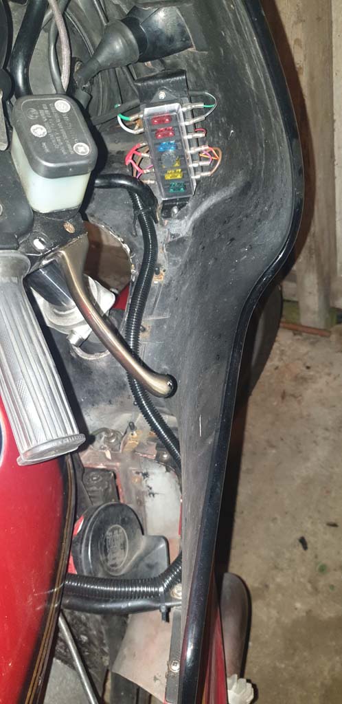
I obtained a proprietory six fuse watertight(ish) fuse box which I located inside the fairing. The box is fixed to a steel plate just behind the right hand indicator where it doesn't foul the handlebars. Fixing is with self tapping screws screwed into thick parts of the fibreglass so it is invisible from the outside.
Next was some flexible corrugated plastic conduit which I ran from a point under the tank to the new fusebox. This I secured to the fairing support for neatness.
Wiring was as follows:
Fuse 1 - A Green wire runs direct from the ignition switch to the fuse. At the switch end, it has both a male and a female lucar so that the original green wire into the headlamp shell can still be connected. On the fused side of the box, a Green/Black wire returns under the dash and into the headlamp shell connecting to the circuit board via a spare connector.
Fuse 2 - A Grey wire runs direct from the ignition switch to the fuse. At the switch end, it has both a male and a female lucar so that the original grey wire into the headlamp shell can still be connected. On the fused side of the box, a Grey/Black wire returns under the dash and into the headlamp shell connecting to the circuit board via a spare connector.
Fuse 3 - This is an auxiliary ground fuse. The bike is fitted with an auxiliary ground loom of my own design that connects the engine mass, the frame ground and the negative of the battery. On second thoughts, it became apparent that a failure of the main engine earth connection would route all of the vehicles ground connections (including the starter) through this wire... ok until you use the starter the bike at which point the wire is likely to burn out...

A fuse in the line prevents this. Brown wires were routed from the undertank area to the fuse an back to the battery via the conduit.
Fuses 4, 5 and 6 Unfused side - Auxiliary circuits - all receive power from a single supply direct from the battery. This red wire is routed via the conduit and splits three ways, one connector for each fuse.
Fuse 4 - Horn. A colour coded wire takes the supply to the relay which is located under the tank via the conduit.
Fuse 5 - Heated Grips. A colour coded wire rakes the supply behind the dash to the switch (non OEM) which is located on the other side of the fairing.
Fuse 6 - Other aux circuits A colour coded wire feeds power to various other circuits including a 12 volt cigar lighter type socket for charging etc.
This is what the installation looks like...

- 20190811_200756 (small).jpg (102.13 KiB) Viewed 4015 times
Rob
 No it's not
  It's a pita to do it
  I already tilt it up for better access to the screw. A longer screwdriver helps too.