Page 1 of 1
Help! I need somebody Help! …
Posted: Tue Sep 06, 2011 6:04 pm
by buffalotankbob
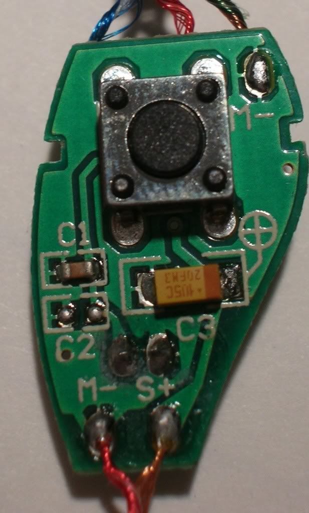
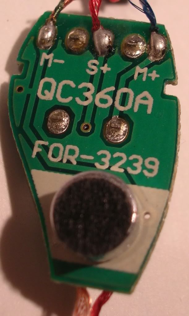
Can anybody identify the electronic components in these photos? I know there’s a push button and condenser microphone… It’s the resistor-like thingie [marked “105C 20FM3”] and the resistor mini-me next to it [by "C1"] that have me stumped...


This is a PTT system for Motorola GMRS radios. If I can learn its secrets I can build a bike-adapted version.
I did this exact thing by dissecting a Midland system. The Motorola version is very complicated by comparison.
What makes this thing so crazy is they combined the PTT and the microphone into one unit… It’s clever and compact.
If I can successfully understand the curcuits, I’ll post the details of how the project turns out.
Why are you doing this? Are you that messed up?
Pretty much.
Purchased a Motocom system for my midland GMRS radios a couple years back for $50+ ‘freekin dollars. It then ‘freekin puked a few weeks into the second riding season. Lotta money for so little joy. Said not gonna do that again. Tore apart the PTT system on one of the cheapo headsets that came with the radios, purchased the parts from RadioShack and built two PTT bike-to-bike systems for under $20.00 [used common earbuds for the speakers].
I hope to do the same once:
1. I understand what the electronic components are, and
2. Understand the circuits.
Thanks for all your help, guyses!
Re: Help! I need somebody Help! …
Posted: Wed Sep 07, 2011 7:28 am
by Ken in Oklahoma
buffalotankbob wrote:Can anybody identify the electronic components in these photos? I know there’s a push button and condenser microphone… It’s the resistor-like thingie [marked “105C 20FM3”] and the resistor mini-me next to it [by "C1"] that have me stumped...
Since you've done this sort of thing before you're obviously handy with electronics, so I don't know if I can be of any help.
The "C1" notation puzzles me since the letter "C" usually designates a capacitor and is then followed by a number designating which one they're talking about. But C1 sure looks like a carbon resistor with color bands designating the value. I'm not able to make out the colors from the pic. Can you?
Just in case you're not familiar with it, here is a resistor color code chart:
http://www.hobby-hour.com/electronics/r ... ulator.php
Presuming CI to be a resistor you could remove the protective coating and cut the etch on one side to isolate the resistor from the rest of the circuit. Then you could directly measure the resistance with a DVM. After you're done measuring the resistance you can solder a thin piece of wire across the gap you made. I would then paint the gap with something like clear varnish.
The C3 thingie looks more like a capacitor to me. (I don't think I've ever seen a square low power resistor before.) I googled the numbers and came up with nothing of course. I'm guessing the letters and numbers are some kind of proprietary notation. I'm also guessing that the value of the cap isn't so important. I'm thinking that it's a coupling capacitor to remove any DC component from the signal while passing the AC (voice) signal itself. If that's the case then the capacitor just needs to be large enough to pass the AC signal. Larger than necessary wouldn't hurt anything and there would be no harm in trying different capacitor values.
But if I'm wrong and C3 is indeed a resistor then you could do the same cutting the etch thing and measure its resistance as well. If I'm right and it's a capacitor I don't know an easy way to measure capacitance with just a DVM.
Editing: the C1 resistor and C3 capacitor (if I've got it right) just might be components of a frequency sensitive circuit where the capacitor would shunt any high frequency component (such radio frequency interference) to ground. The resistor would help "tune" the circuit and perhaps reduce the signal to the level needed by the next stage of the electronics. But I'm still inclined to think the C3 capacitor is a coupling capacitor. But either way, you're not likely to hurt anything by playing around with the values.
Ken
Re: Help! I need somebody Help! …
Posted: Wed Sep 07, 2011 7:56 am
by DanielMc
Can't contribute to the intelligent debate, but reading about stuff well outside my level of understanding reminded me of the sketch below...
http://www.youtube.com/watch?v=THNPmhBl-8I
Re: Help! I need somebody Help! …
Posted: Wed Sep 07, 2011 8:06 am
by buffalotankbob
Ken,
thanks so much for your response. Actually, I am electronically semi-literate, sad to say. I know there are various components [resistors, capacitors, etc.] and that the the current travels through various paths [circuits?]. I knew enough to look up the resistor value for the last project and went to radioshack and matched up the parts. Their design was simple enough for me to "monkey see, monkey do" my way through it.
With the kind assistance of fellow airheads such as you, I hope to be able to understand the basic components and the order in which to arrange them.
Your help is greatly appreciated.


