Why Boge Shocks Die
Posted: Mon Nov 17, 2014 6:18 pm
Well, after replacing the shocks on my ’78 R100/7, I was curious as to why my OEM Boge shocks died. The bike had only 13,000 miles on it when I got it late in the summer. So, it certainly was not excessive wear from use. Could age along have been a factor? I decided I needed to know.
When I first bought the bike and did my usual detailing operation, I removed the shocks, took them apart, cleaned and polished all the bits. I have to say that when I was done, they looked like new. Unfortunately, when I had the shock bodies in my hands, one seemed to be low on fluid, although was quite smooth in action, and the other was very sticky and when fully collapsed, did not want to extend again. I had to put the shaft in my vise, put a rod thru the bottom mount and tug and pull until it was fully extended. Another thing I noticed was that one spring was loose with the pre-load adjuster on the softest setting. So, I compared the extended length of the two bodies and the sticky one was about ¼ shorter than the smooth acting one. Part numbers on the bodies were identical.
The smooth one as I mentioned, seemed to be low on fluid. I assumed this because when fully extended, I could move the rod in and out about an inch or more with no damping to speak of. Further compression would result in damping and extending it out from there would also exhibit damping.
Since the shocks are not rebuildable, the only way to get inside is to cut them apart. So, I put one in my lathe and machined back the rolled over top until I started to see oil seeping out. I tapped it with a small hammer and chisel and the cap separated. I was then able to remove the internals from the body. I did this with both shock bodies.
Here is what I found inside.
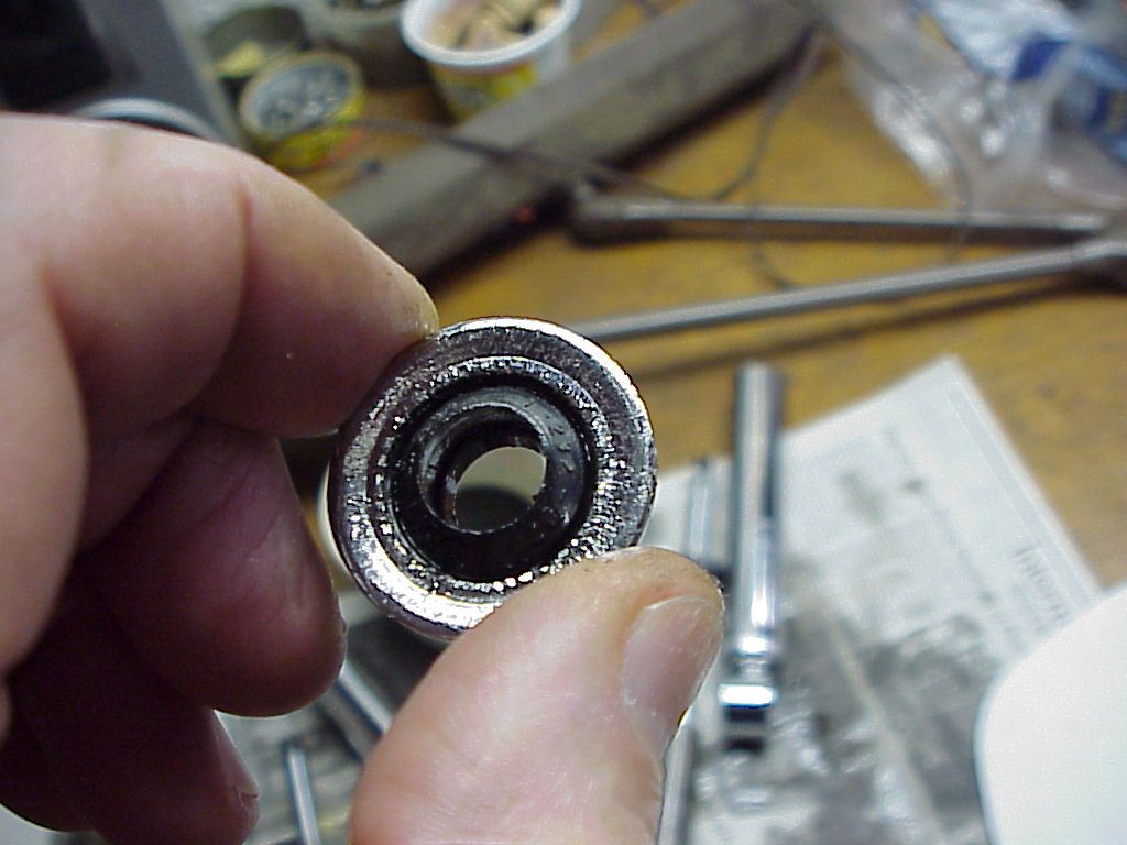
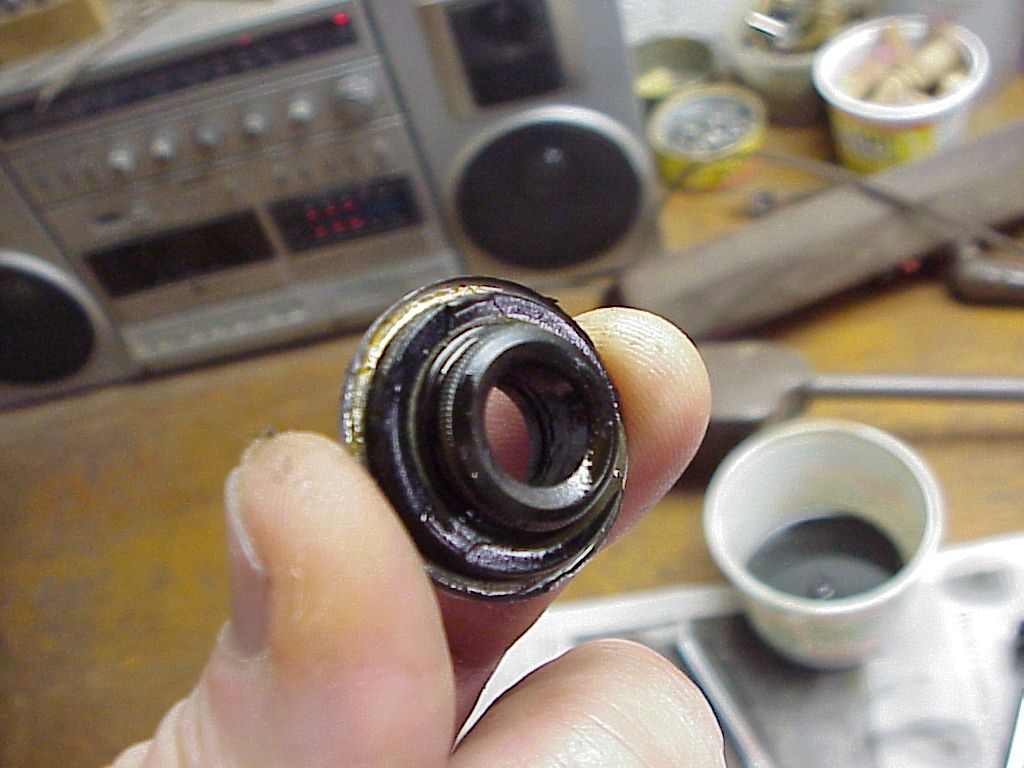
Top oil seal
The seal that I though was bad and had let fluid escape appears to have been fine. It does not appear that the shock was low on fluid. More on that later. Here is the seal. It appears to be bonded to the rolled top of the shock body. Perhaps the rolling process causes the seal and the top to bond together. I did not try to separate them.
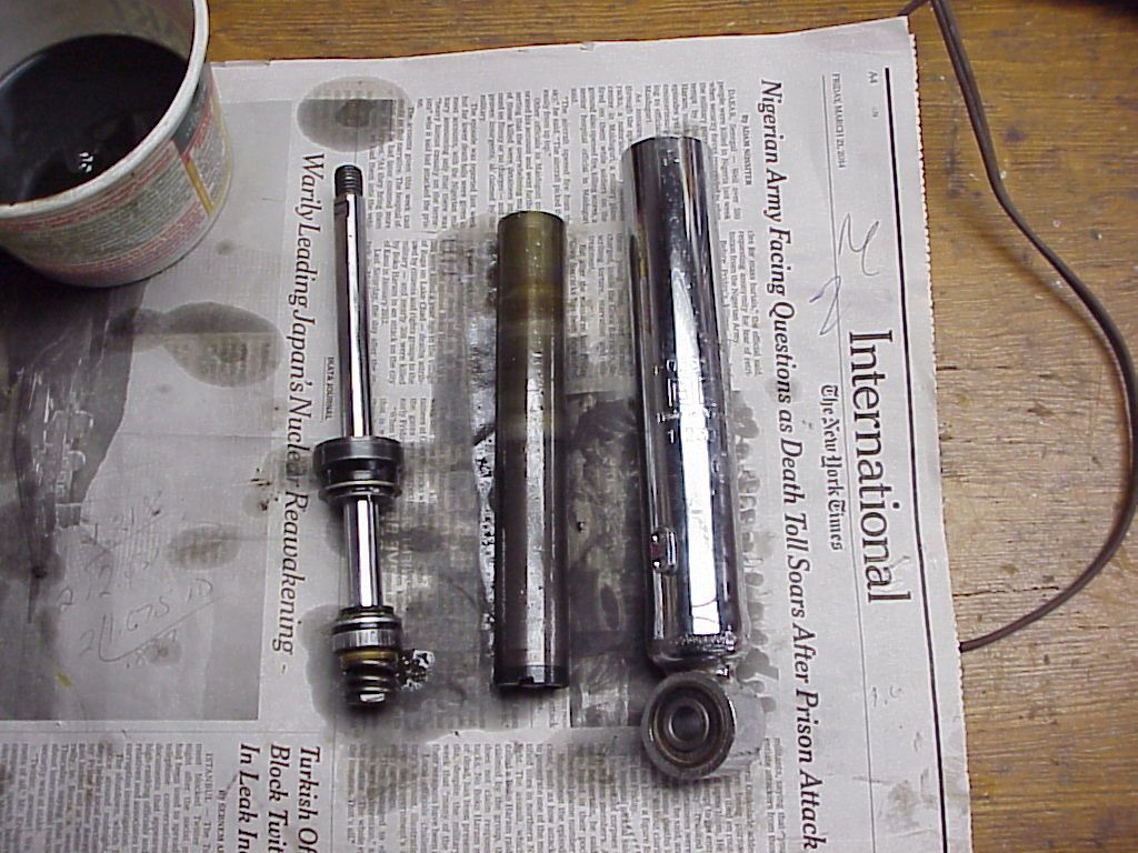
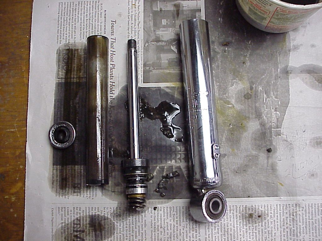
Internals
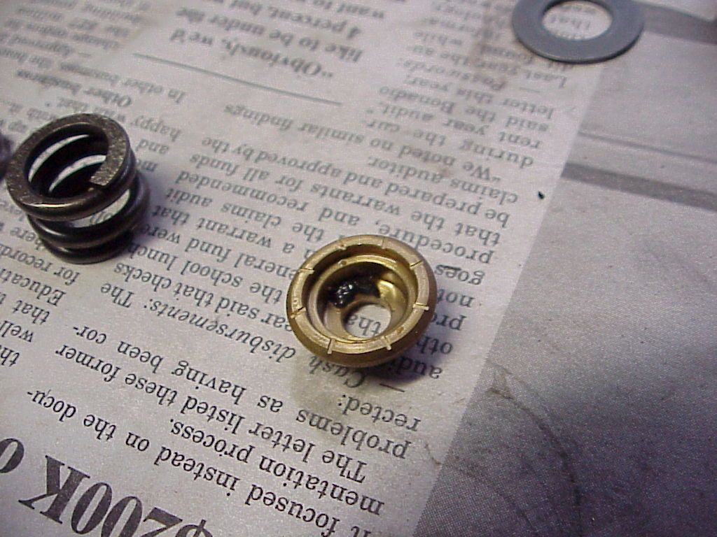
Here is what I found when I opened the smooth acting and ¼ longer stroke shock. It looked normal, except for some small, gritty debris around the lower valve. Not a lot of debris was visible. But it should not be there.
Here is a close-up of the top side of the valve and you can see some of the debris.
This debris reminded me of similar debris that I had found inside my front forks. In the case of the forks, it turned out to be the bumper in the slider had deteriorated and crumbled. But, there was a lot of debris like inside the forks. So, I was not sure at this point, what was the source.
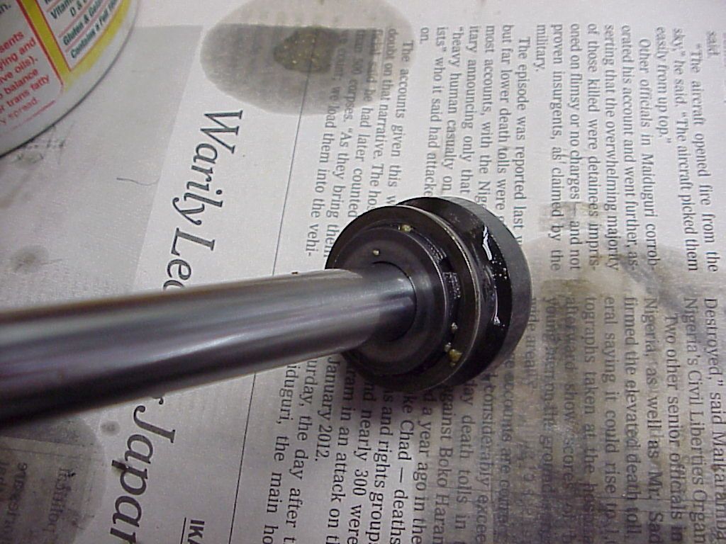
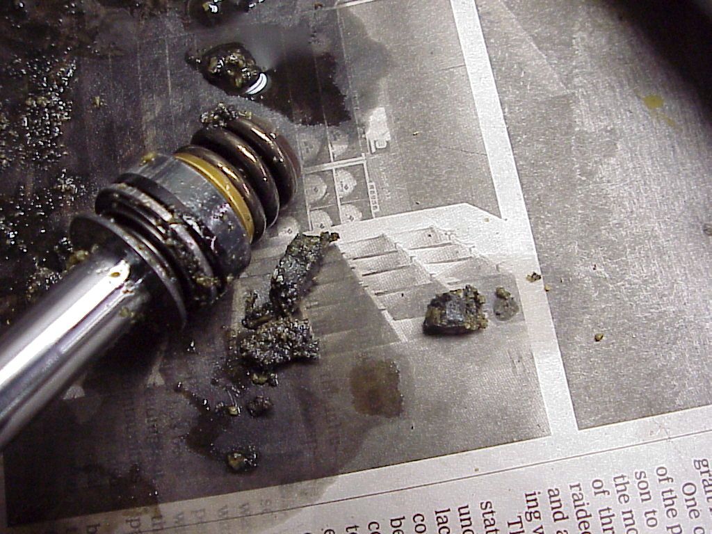
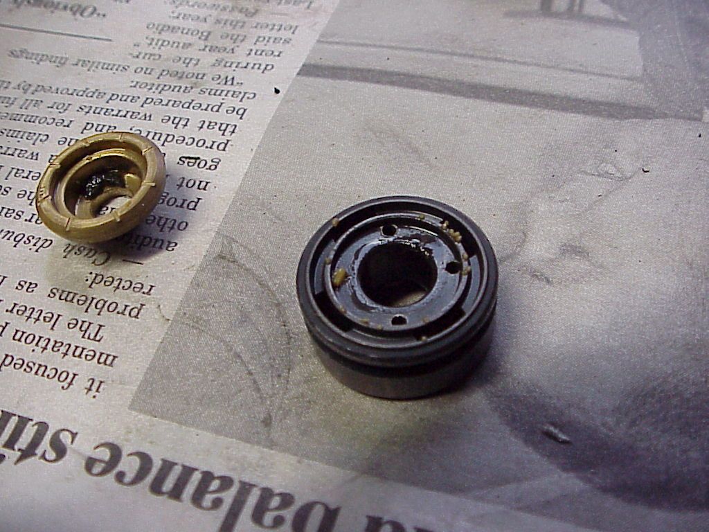
So, I cut into the next shock and pulled it apart. Big difference. There was what appeared to be a bumper in the lower valve assembly. However, when I touched it, it crumbled into pieces. I tried to pick up a big piece and it just crumbled further in my fingers. So, I left it alone and took this picture.
The debris between the rod and the shock body, next to the valve is what is left of the internal bumper. It belongs between the two thin washers that can be seen in the center of the valve. Note that on the first shock I opened, those two washers were touching each other. That accounts for the ¼” difference in stroke.
Here is a closer look at what is left of that bumper.
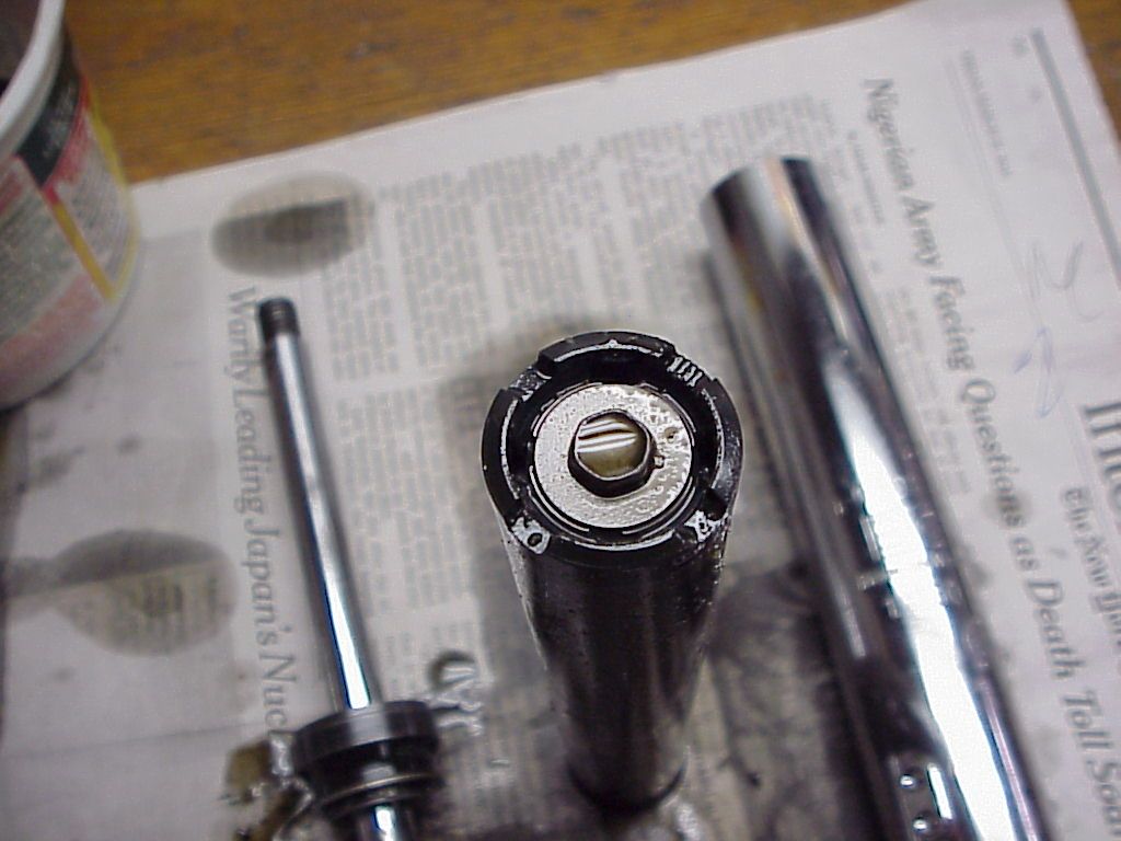
Looking closer at the valve from the second shock, you can see how the crumbs from the bumper are filling the ports in the top guide of the valve. This is how oil gets thru that guide. If the ports are plugged, the shock becomes hydraulically locked. Some of the ports were so packed with debris, I had to dig it out with a dental pick. Here is a closer look at the area where the bumper should have been.
After finding this condition in the 2nd shock, I took a look down into the cylinder for the 1st shock. There at the bottom of the cylinder resided the rest of the crumbs that were once the shock bumper.
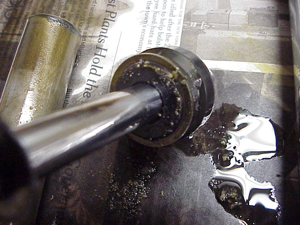
Now, there is more valving involved with these shocks than what just on the rod. Looking back at the photos of the internals, you’ll see a long tube included. This is the cylinder mentioned above and inside which the rod/valve assembly slides. Mounted into the bottom of the cylinder is a cap that contains a small disc valve. Here’s a photo of that valve, viewed looking up at the bottom of the cylinder.
When the shock is compressed, oil is pushed out thru this disc valve as part of the porting process. When the shock rebounds, this valve closes, yet there are still ports which are not covered and that allow oil to return, only at a slower rate than it departed from the bottom of the cylinder. Although describing how this shock works hydraulically is not part of this article, I believe this valve is a relief valve for severe shock loads which need additional relief to allow the shock to compress in reaction to a severe bump. So, if that valve does not close, rebound damping is lessened because the oil can flow back in the way it came out. It only takes one crumb to hold the disc away from its seat and open more than one port to oil flow.
I next put the parts into the parts washer to clean off the debris and remove any oil. With that done, I put the each of the shafts in the vise and took the valves apart. Each valve at the bottom of the shaft is actually a piston and two disc valves. The piston acts as the ported seats for both valves. One has a brass valve with slots cut as small relieve ports that are open even when the valve is closed. The other is a thin spring steel disc valve.
First, was to remove the nut and heavy spring on the brass valve. Here is what I found. Note the crud inside the brass valve. It was a jelly-like substance. Note sure what it actually was.
Under that valve was another nut that held the piston in place. With that removed, the piston could be taken off the rod, followed by the thin, spring steel disc valve and it’s spring. I found this on the steel disc side of the piston. Note that one of the small ports is plugged with debris.
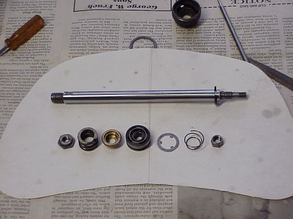
Here are all the parts that make up the valve that is mounted to the rod, short of the o-ring seal that fits in the o-ring groove of the piston in the center of the valve. You can see the o-ring (more on this below) in the first photos of the internals. The rings are still mounted in the piston in the center of the rod valve in those pictures.
From left, retaining nut, spring, brass valve, piston (and valve seats for brass and steel disc valve), valve disc, spring, retaining nut.
From this you can see that this valve controls oil flow around the piston in both compression and rebound and alters the flow during those two strokes. Note how light the spring for the disc valve is which operates during compression and how heavy the spring is for the brass which operates during rebound.
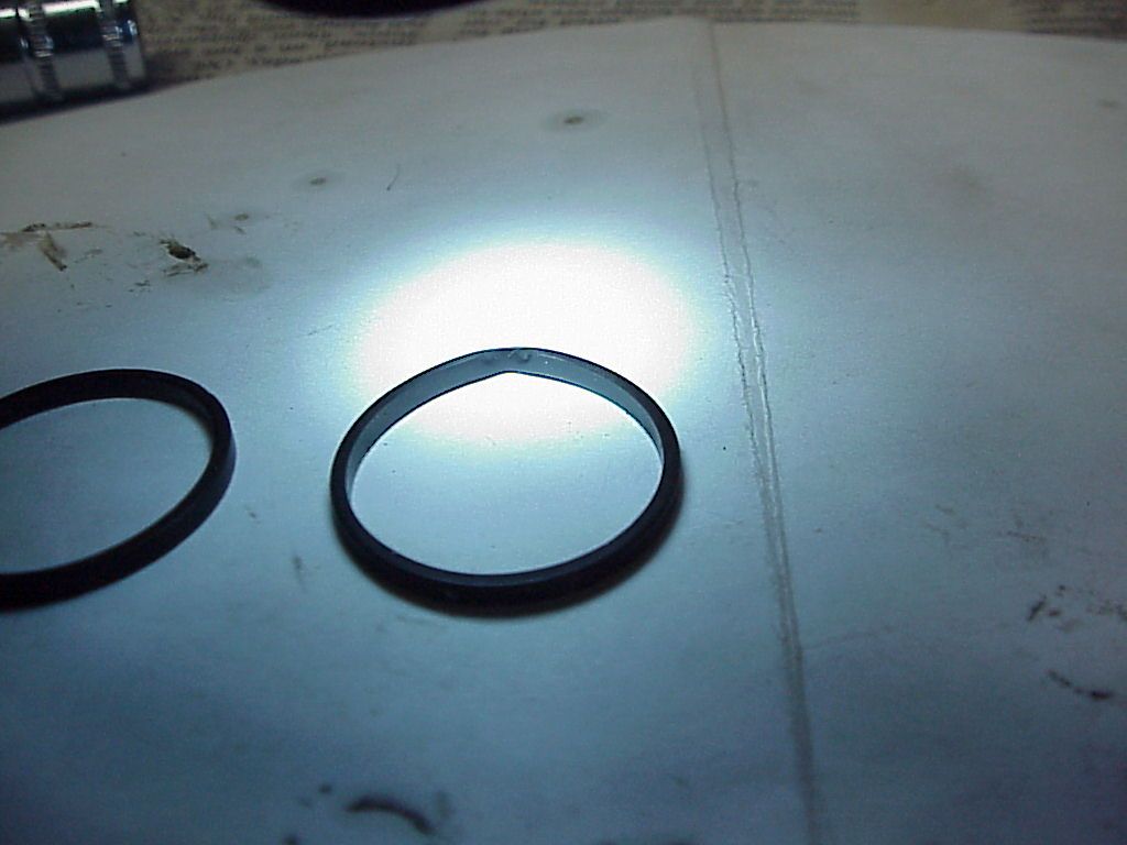
Lastly, are the o-rings. As removed, these were square cross-section o-rings. Looking at them closely, does not reveal if they started life as round section o-rings. I’ve seen o-rings become square like this over time when compressed in other applications on British bikes. So, I suspect these were round o-rings when they were new, but cannot say that with 100% confidence.
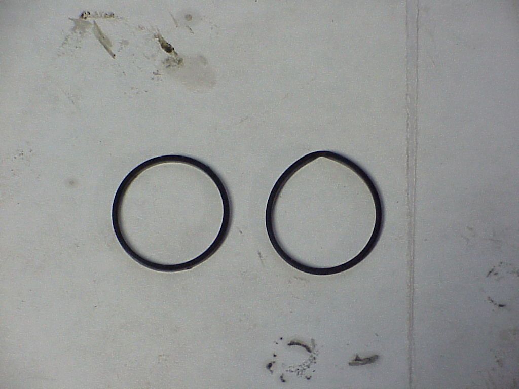
Note that one of the rings is deformed. It appears that it had swelled over time and extruded out of the groove. Or, perhaps it was pinched when the shock was originally assembled, hard to say. But, it definitely had a negative effect on how that particular shock operated. That o-ring was in the sticky shock body and this could very well be why it was sticky. The o-ring sticking out of the groove would act like a wedge in one direction. And as explained above, that shock would compress fine, but fight me when I tried to extend it back out. If I jiggled it as I pulled it would extend. Jiggling it would more than likely put the ring in and out of the groove each time. Here is a closer look at the ring distortion.
Conclusions based on findings
I believe that the deterioration of the bumpers is what killed these shocks and probably kills or has killed every Boge shock out there. Although the distorted o-ring certainly had a negative effect on the one shock, whether or not that had happened would have meant little when it comes to the finite life of the shock.
After looking at the internals, these were well designed and well-made shocks. I would say that had they not been permanently sealed by rolling the edge on the body, they would have been very easy to rebuild. Two new o-rings and two new bumpers and these shocks would have been good as new.
I will not throw these shock bodies away. I might find myself fresh out of projects in the dead of winter and revisit these shocks. I believe that I can skim the chrome off where I cut them apart and thread the OD of the shock. I can machine a mating cap and thread it internally. I would need to find a properly sized seal for the shaft and mount that in the cap as well. There is more than enough room within the ID of the spring to accommodate a cap of slightly larger OD than the shock body.
My last conclusion is, based on what I found inside these two shocks, I would not consider buying used Boge shocks or even NOS ones for that matter. I suspect it is the oil that destroys the bumper inside and once that happens, the shock body is useless. So even a NOS that has never seen use, probably has a bumper that has deteriorated and it just waiting to be exercised so the crumbs can plug the ports or block open the disc valves.
regards,
Rob
When I first bought the bike and did my usual detailing operation, I removed the shocks, took them apart, cleaned and polished all the bits. I have to say that when I was done, they looked like new. Unfortunately, when I had the shock bodies in my hands, one seemed to be low on fluid, although was quite smooth in action, and the other was very sticky and when fully collapsed, did not want to extend again. I had to put the shaft in my vise, put a rod thru the bottom mount and tug and pull until it was fully extended. Another thing I noticed was that one spring was loose with the pre-load adjuster on the softest setting. So, I compared the extended length of the two bodies and the sticky one was about ¼ shorter than the smooth acting one. Part numbers on the bodies were identical.
The smooth one as I mentioned, seemed to be low on fluid. I assumed this because when fully extended, I could move the rod in and out about an inch or more with no damping to speak of. Further compression would result in damping and extending it out from there would also exhibit damping.
Since the shocks are not rebuildable, the only way to get inside is to cut them apart. So, I put one in my lathe and machined back the rolled over top until I started to see oil seeping out. I tapped it with a small hammer and chisel and the cap separated. I was then able to remove the internals from the body. I did this with both shock bodies.
Here is what I found inside.
Top oil seal
The seal that I though was bad and had let fluid escape appears to have been fine. It does not appear that the shock was low on fluid. More on that later. Here is the seal. It appears to be bonded to the rolled top of the shock body. Perhaps the rolling process causes the seal and the top to bond together. I did not try to separate them.


Internals
Here is what I found when I opened the smooth acting and ¼ longer stroke shock. It looked normal, except for some small, gritty debris around the lower valve. Not a lot of debris was visible. But it should not be there.

Here is a close-up of the top side of the valve and you can see some of the debris.

This debris reminded me of similar debris that I had found inside my front forks. In the case of the forks, it turned out to be the bumper in the slider had deteriorated and crumbled. But, there was a lot of debris like inside the forks. So, I was not sure at this point, what was the source.
So, I cut into the next shock and pulled it apart. Big difference. There was what appeared to be a bumper in the lower valve assembly. However, when I touched it, it crumbled into pieces. I tried to pick up a big piece and it just crumbled further in my fingers. So, I left it alone and took this picture.

The debris between the rod and the shock body, next to the valve is what is left of the internal bumper. It belongs between the two thin washers that can be seen in the center of the valve. Note that on the first shock I opened, those two washers were touching each other. That accounts for the ¼” difference in stroke.
Here is a closer look at what is left of that bumper.

Looking closer at the valve from the second shock, you can see how the crumbs from the bumper are filling the ports in the top guide of the valve. This is how oil gets thru that guide. If the ports are plugged, the shock becomes hydraulically locked. Some of the ports were so packed with debris, I had to dig it out with a dental pick. Here is a closer look at the area where the bumper should have been.

After finding this condition in the 2nd shock, I took a look down into the cylinder for the 1st shock. There at the bottom of the cylinder resided the rest of the crumbs that were once the shock bumper.
Now, there is more valving involved with these shocks than what just on the rod. Looking back at the photos of the internals, you’ll see a long tube included. This is the cylinder mentioned above and inside which the rod/valve assembly slides. Mounted into the bottom of the cylinder is a cap that contains a small disc valve. Here’s a photo of that valve, viewed looking up at the bottom of the cylinder.

When the shock is compressed, oil is pushed out thru this disc valve as part of the porting process. When the shock rebounds, this valve closes, yet there are still ports which are not covered and that allow oil to return, only at a slower rate than it departed from the bottom of the cylinder. Although describing how this shock works hydraulically is not part of this article, I believe this valve is a relief valve for severe shock loads which need additional relief to allow the shock to compress in reaction to a severe bump. So, if that valve does not close, rebound damping is lessened because the oil can flow back in the way it came out. It only takes one crumb to hold the disc away from its seat and open more than one port to oil flow.
I next put the parts into the parts washer to clean off the debris and remove any oil. With that done, I put the each of the shafts in the vise and took the valves apart. Each valve at the bottom of the shaft is actually a piston and two disc valves. The piston acts as the ported seats for both valves. One has a brass valve with slots cut as small relieve ports that are open even when the valve is closed. The other is a thin spring steel disc valve.
First, was to remove the nut and heavy spring on the brass valve. Here is what I found. Note the crud inside the brass valve. It was a jelly-like substance. Note sure what it actually was.

Under that valve was another nut that held the piston in place. With that removed, the piston could be taken off the rod, followed by the thin, spring steel disc valve and it’s spring. I found this on the steel disc side of the piston. Note that one of the small ports is plugged with debris.

Here are all the parts that make up the valve that is mounted to the rod, short of the o-ring seal that fits in the o-ring groove of the piston in the center of the valve. You can see the o-ring (more on this below) in the first photos of the internals. The rings are still mounted in the piston in the center of the rod valve in those pictures.
From left, retaining nut, spring, brass valve, piston (and valve seats for brass and steel disc valve), valve disc, spring, retaining nut.

From this you can see that this valve controls oil flow around the piston in both compression and rebound and alters the flow during those two strokes. Note how light the spring for the disc valve is which operates during compression and how heavy the spring is for the brass which operates during rebound.
Lastly, are the o-rings. As removed, these were square cross-section o-rings. Looking at them closely, does not reveal if they started life as round section o-rings. I’ve seen o-rings become square like this over time when compressed in other applications on British bikes. So, I suspect these were round o-rings when they were new, but cannot say that with 100% confidence.

Note that one of the rings is deformed. It appears that it had swelled over time and extruded out of the groove. Or, perhaps it was pinched when the shock was originally assembled, hard to say. But, it definitely had a negative effect on how that particular shock operated. That o-ring was in the sticky shock body and this could very well be why it was sticky. The o-ring sticking out of the groove would act like a wedge in one direction. And as explained above, that shock would compress fine, but fight me when I tried to extend it back out. If I jiggled it as I pulled it would extend. Jiggling it would more than likely put the ring in and out of the groove each time. Here is a closer look at the ring distortion.

Conclusions based on findings
I believe that the deterioration of the bumpers is what killed these shocks and probably kills or has killed every Boge shock out there. Although the distorted o-ring certainly had a negative effect on the one shock, whether or not that had happened would have meant little when it comes to the finite life of the shock.
After looking at the internals, these were well designed and well-made shocks. I would say that had they not been permanently sealed by rolling the edge on the body, they would have been very easy to rebuild. Two new o-rings and two new bumpers and these shocks would have been good as new.
I will not throw these shock bodies away. I might find myself fresh out of projects in the dead of winter and revisit these shocks. I believe that I can skim the chrome off where I cut them apart and thread the OD of the shock. I can machine a mating cap and thread it internally. I would need to find a properly sized seal for the shaft and mount that in the cap as well. There is more than enough room within the ID of the spring to accommodate a cap of slightly larger OD than the shock body.
My last conclusion is, based on what I found inside these two shocks, I would not consider buying used Boge shocks or even NOS ones for that matter. I suspect it is the oil that destroys the bumper inside and once that happens, the shock body is useless. So even a NOS that has never seen use, probably has a bumper that has deteriorated and it just waiting to be exercised so the crumbs can plug the ports or block open the disc valves.
regards,
Rob